In the previous section we saw that the spacing of stirrups should not be greater than 300 mm at any part of our beam. Now we will calculate the spacing for the region from A to E.
For calculating the spacing, we use the basic Eq.13.58
Vus =Vu -τcbd
Vu is the shear force at the critical section =52.29 kN
τc = 0.5745 N/mm2
So we get Vus = -960.405 N
We are getting a negative value. This is so because, as seen from the graph, the critical section falls to the right of E. It can be further explained as follows: We have seen that the portion between A and F need to be designed for 52.29 kN only. But this is less than Vuc which is equal to 53.25 kN. This means the applied factored shear at the critical section is less than even the shear capacity contributed by concrete. So we can give a constant spacing of 300 mm through out the length of the beam. Because, for our beam, we have confirmed that the spacing at any point should not be less than 300 mm.

Design shear strength of concrete in slabs:
The behaviour of slabs and shallow beams under the action of shear forces have been studied through experiments. The results of those experiments show that the slabs and shallow beams can take up a higher shear stress than applicable to beams of usual proportions. This means that the contribution from concrete is more in these cases. So the code allows us to increase τc, given in table 19. This increase is effected by multiplying it with a factor k, given in cl.40.2.1.1 of the code.
K depends on only one factor, which is D, the overall depth of the section. From the table, we can see that when D = 300 mm, K becomes equal to 1, which means that at D= 300 mm and above, the concrete of the section will not give the extra shear strength attributed to slabs and shallow beams.
If we closely examine the values given in the table in the above clause, we can see that the value of k can be written in the following method also:
• k= 1.3 when D is less than or equal to 150 mm
• k= [1.6 -(0.002D)] when D falls between 150 and 300mm (should not be equal to 150 or 300)
• k=1 when D is greater than or equal to 300 mm
Where D is the overall depth of the slab in mm
It should be noted that the above values are applicable only to solid slabs. They cannot be used for ribbed slabs, waffle slabs, flat slabs etc., (Details about these special types of slabs can be seen by scrolling down to items 3, 4 and 5 of the web page given here)
Now we can do a problem demonstrating the shear design of a slab. We will do this for a slab for which we have already done the flexure design. So we will revisit Solved example 6.1 which is given towards the end of chapter 6 – Design of One-way slabs.
Solved example 13.3
Design a One-way slab with a clear span of 3.5 m, simply supported on 230 mm thick masonry walls. The loads other than self weight acting on the slab are the following:
• Live load 2.5 kN/m2
• Surface finish 1 kN/m2
Assume that the slab is subjected to moderate exposure conditions. Assume Fe 415 steel.
Solution:
We have already done the design for flexure of this problem. From that we will get the following details:
• Total slab thickness D = 180 mm
• Effective depth d = 145 mm
• fck = 25 N/mm2
• pt at mid span = 0.301
• pt at the support = 0.301/2 = 0.1505 (Alternate bars are bent up. So only half of the bars at mid span will be present at the support)
• Effective span l= 3645 mm
• Total factored load wu(DL+LL) = 12 kN/m
Here we are going to check whether the slab is safe in shear. We are going to do this check at the support, which is the section having the maximum value of shear force. If it is safe at the support, it will be safe at all other sections also. So there is no need to consider the different positions of the LL, to obtain the maximum shear force at other sections.
Another point to note is that, the load applied on the slab will be in kN/m2. We have converted it into kN/m while doing the flexure design. This same load is to be used for shear check also because, we are checking the shear at the support of a '1000 mm wide strip of the slab', which is considered as a 'beam of width b = 1000 mm and overall depth D'
With the above data, we can do the shear check as shown below:
Vu at the support =wu l / 2 = (12 x 3.645) /2 = 21.87 kN
From table 19, value of τc for a pt of 0.1505 is equal to 0.2904 N/mm2
This can be increased by multiplying by k. So we have to find the value of k.
• D =180 mm (falls between 150 and 300)
• So, from 13.66 above, k = [1.6 -(0.002 x180)]= 1.24
• Thus, the contribution from concrete = Vuc = k times τc x bd=1.24 x 0.2904 x 1000 x 145 = 52.2 kN.
• This is greater than Vu = 21.87 kN.
So the slab is safe in shear.
Members subjected to axial force in addition to shear force
Consider the beam shown in fig.13.77 below:Fig.13.67
Beam subjected to axial compressive force

It is subjected to an axial compression, in addition to shear and flexure. This type of loading in which axial tensile or compressive loads are present may occur due to a variety of reasons.
• Presence of actual external axial loads
• Longitudinal prestressing of the member
• Restraining axial forces developed due to shrinkage of concrete or temperature changes
The shear strength of a beam will be modified due to the presence of axial tension or compression. This modification in pre-stressed beams is treated by different principles. We will discuss here only about ordinary beams.
When we discussed the basics about shear on a beam, we saw the forces acting on the particles of the beam. We have seen fig.13.8 which showed the various forces on the particles. If an axial force is also acting on the beam, then the forces shown in the fig.13.8 will be modified. The angle α of the principal plane, and the magnitude of the principal tensile stress which causes the diagonal tension crack will also change.
Axial compression will increase the shear capacity of concrete in a beam. And axial tension will cause a decrease in the shear capacity of concrete in a beam.
So when a beam is subjected to an axial compressive force in addition to flexure and shear, the code allows us to increase the value of τc by multiplying it with a factor denoted as δ. It’s value is given in cl.40.2.2 of the code as
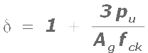
The value of δ calculated from the above equation should be compared with '1.5'. If it is found to be greater than 1.5, then δ should be taken as equal to 1.5. If the calculated value is less than 1.5, then we can use it. In other words, δ should be taken as the lesser of:
• value calculated using Eq.13.67 and• 1.5
In the above Eq.13.67,
• pu is the factored axial compressive force in N
• Ag is the gross area of the section in mm2
• fck is the characteristic strength of concrete in N/mm2
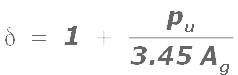
When an axial tension is present, we must decrease τc using a reduction factor. But the code does not mention about the case of axial tension. We can use the following expression based on ACI code in such a situation:
Eq.13.68:
No comments:
Post a Comment