In the previous section we saw 'vertical shear reinforcements'. Now we will see 'Inclined shear reinforcements'.
Inclined shear reinforcement

The inclined stirrups should be placed in such a way that they intercept the cracks nearly at right angles. Such an arrangement will resist the widening and propagation of the cracks. These stirrups are usually inclined at 45o with the main bars of the beam. An angle less than 45o is not recommended because they may slip along the longitudinal bars of the beam.
Inclined stirrups are most effective in reducing the width of the inclined cracks. In cases were beams are subjected to high axial tensile forces, there will be formation of transverse cracks which will extend to the full depth of the beam. Also such cracks will be perpendicular to the beam axis. So the inclined stirrups will effectively intercept those cracks.
But in the case of beams subjected to seismic loads, the direction of shear force may get reversed. In such beams, the inclined stirrups will be entirely ineffective. For such beams, special provisions for shear design should be made. We will discuss about it in a later chapter.
Next we see the bent-up bars
Fig.13.30
Shear reinforcement using bent-up bars

This is provided by bending up one or two main bars. In the above fig, the bent-up bar is shown separately from the main tensile steel only for clarity. The vertical distance between the bottom most surface of the bent-up bar and that of the other main tensile steel is shown to be 0 mm. This indicates that both the bars belong to the same layer.
Just as in the case of inclined stirrups, the direction of bent-up should be in such a way that they intercept the crack nearly at right angles. Also the bar should be properly anchored. That is., the length of this bent-up bar, beyond the midpoint of the inclined portion should not be less than the ‘development length’ of the bar. This is shown in the fig.13.31 given below. We will learn about development length in later chapters.
Fig.13.31
Development length for bent-up bar

In the design process of a beam, first we determine the main tensile bars required to resist the bending moment. Out of these bars, we bent one or two to resist shear near the supports. The bars at the bottom corners are not bent. They remain 'straight', and are extended from support to support to anchor the stirrups properly. It can also be seen that beyond the bottom point of bent, the bent-up bar is no longer available at the tension zone of the beam. In general, this does not cause a problem because nearer the supports, the Bending moment (sagging type) is of a lesser magnitude, and so all the bars will not be required there. However in every design process, it is important to ensure that the bent-up bars are no longer required beyond the point of the bent, and that development length requirements are satisfied.
We have to consider another point while using bent-up bars for shear reinforcement. That is., the design should not be in such a way that all the design shear load is resisted by the bent-up bars alone. We must provide stirrups also. Cl.40.4 of the code specifies that 'Where bent-up bars are provided, their contribution towards shear resistance shall not be more than half that of the total shear reinforcement.' For example, if a factored shear force of 30 kN has to be resisted at a section, all the bent-up bars at the section together should provide a resistance of 15 kN only. If the bent-up bars given is capable of giving a resistance greater than 15 kN, the stirrups provided at the section should also be capable of giving a resistance equal to or greater than 15 kN.
Now that we have seen the various methods of providing shear reinforcement, we will now discuss the procedure to design them.
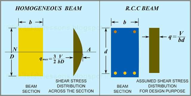
For designing the reinforcements, first we have to determine how much shear stress will have to be resisted at a given section in a given beam. We have seen that the stress which causes the crack near the support at the NA is equal to the shear stress q at the section. (Details here) So now we revisit fig.13.5. There we saw that the shear stress follows a parabolic distribution, and that the peak point of the parabola is at the NA. In the strength of materials lessons, we have learnt that this maximum value is given by:
Eq.13.11: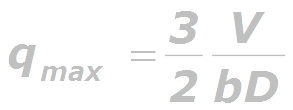
This is the maximum value at a single layer, which is the Neutral layer. At other points the values are different. Also, the actual distribution in a reinforced concrete beam section is quite complex due to the presence of steel reinforcements. So the code assumes a uniform stress across the section, and it’s value is given by:
Eq.13.12:


• V =Shear force at the section, • b =width of the section, and • d =effective depth of the beam. This can be represented by the following fig.13.32:
Fig.13.32
Comparison of shear stresses
Eq.13.13:

When we learned about the behaviour of the beam in flexure (bending), we used the terms such as:
• Bending moment M calculated using the characteristic loads,
• Factored bending moment Mu calculated using factored loads, and
• Ultimate moment of resistance MuR of the section.
In similar lines, for the behaviour of beam in shear we can define V, Vu , and VuR
• V is the shear force at the section due to the characteristic loads applied on the beam.
• We multiply V by the appropriate factor to get the factored shear force Vu.
• We must design the section in such a way that the ultimate shear resistance VuR offered by the section is greater than Vu.
Based on the above Eq.13.13, the shear stress at the point of impending failure, denoted as τv is given by:

Eq.13.14 is given in Cl.40.1 of the code. So now we know the shear stress for which we have to make the design. Before proceeding into the design steps, we shall derive a modified form of the above equation, to be used in case of beams of varying depth. We will do this in the next section.
Great Article… I love to read your articles because your writing style is too good, its is very very helpful for all of us and I never get bored while reading your article because, they are becomes a more and more interesting from the starting lines until the end.
ReplyDeletehydraulic services
I wanted to thank you for this great read!! I definitely enjoying every little bit of it I have you bookmarked to check out new stuff you post.
ReplyDeleteFabrication equipment
Angle BarGet steel products of various dimensions and for a wide range of industries and applications. We offer the best steel chequered plates, steel hollow sections, ms channels, ms plates, flat bar and angle bar online in Singapore.
ReplyDeleteThank you for sharing this blog. Very useful blog for me. We providing the best steel plate, steel bar, steel section, steel pipes online at affordable prices.
ReplyDeleteAngle Bar
Thank you for sharing this blog. Get steel products of various dimensions and for a wide range of industries and applications. We offer the best steel chequered plates, steel hollow sections, ms channels, ms plates, flat bar and angle bar online in Singapore.
ReplyDelete