In the previous section we completed the discussion on 'the calculation of the design shear stress at a beam section'. We do not have to provide reinforcements to resist this exact 'design shear stress'. This is because, there is another 'force' that will act in a direction opposite to the applied external shear force. In this section, we will see the details about this new 'force'.
Design shear strength of concrete in beams
The new 'force' is none other than the one obtained from the 'interlocking between the aggregates' of the concrete. It is denoted as Va, and is shown in fig.13.43 below:
Fig.13.43
Force Va due to interlocking of aggregates

Let us assume that a beam is separated into two parts. Due to the applied external forces, the two parts will slide past each other. But such a sliding will be resisted by the interlocking of the aggregates at the interface of the two parts. So there is a 'resisting force' which opposes the sliding. This resisting force is Va. The vertical component of Va, shown in the fig. above as Vay will contribute towards resisting the external shear force at the section. Va depends upon the grade of concrete (M20, M25 etc.,), because, stronger the concrete, greater will be the interlocking force.
Va also depends up on the 'extent of cracking'. Because the aggregates interlocking will not work well along cracks. Now, we have seen the cracks due to diagonal tension, and also the cracks due to bending. The former forms mainly near the supports, and the latter forms near the midspan at the bottom most tension fibres, and propagates upwards. When the loading is increased, this latter type will be seen not only at the midspan region, but also towards the sides, as shown in fig.13.44 below:
Fig.13.44
Flexural cracks

But we know that the 'tensile steel' provided at the bottom of the beam is very effective in controlling this flexural cracks. Thus we can see that the quantity of tensile steel plays a role in controlling cracks, and the cracks play a role in the magnitude of Va. That is:
• Aggregate interlocking depends on cracks. Greater the cracks, lesser the interlocking.
• Cracks in turn, depends on 'quantity of tensile steel'. Greater the steel, lesser the cracks.
• So the inter locking depends on 'quantity of tensile steel'. We can say that quantity of tensile steel plays a role in determining the magnitude of Va.
There is yet another force that will resist the sliding of two parts of a beam. It is the dowel force Vd in the tensile steel. This is shown in fig.13.45 below:
Fig.13.45
Dowel force in tensile steel

The tensile steel acts as a 'dowel' or 'pin' connecting the concrete blocks on either sides of the crack. Due to this action, the blocks are prevented from sliding past each other. While performing this task , the steel will experience a vertical force Vd as shown in the fig., and this force is known as the 'dowel force'. Naturally, this dowel force will depend upon the quantity of tensile steel provided.
Thus the new 'force' that we mentioned above, depends upon the grade of concrete, and quantity of tensile steel. This force is commonly referred to as the 'Design shear strength of concrete in beams', and denoted by τc. The code uses the following empirical formula to calculate τc:
Eq.13.32:
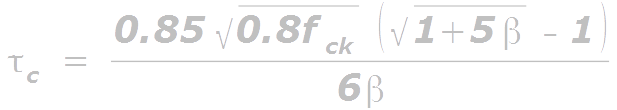
In the above formula, β should be given the largest value among (i) and (ii) given below:

pt is the ‘percentage of tensile steel’ given by
Eq.13.33:
Eq.13.32 is given in 39.2.1 of SP 24. But we do not have to use this formula directly. The values are given in table 19 of the code, and intermediate values can be obtained by linear interpolation.
An important point is to be noted while using the values in table 19. We know that the quantity of tensile steel is being taken into account, in determining the values given in the table. So if at a region, 'bar cutoff' has been applied, the above values can be used only if detailing requirements are satisfied. We will learn more details about it when we discuss about 'curtailment of bars' in a later chapter.
So, knowing the values of the grade of concrete, and the percentage of tensile steel, we can calculate the stress τc (from table 19) which the concrete will be able to take. Multiplying this stress by the area, we will get the force that concrete will offer in resisting the shear. Thus, this force, denoted by Vuc , is obtained using the following equation:
We must note that τc given by the code is the 'design' shear stress. That means the required 'factor of safety' has been already applied while using Eq.13.32, and it is the shear stress offered by the concrete at the point of impending failure. The code (clause 40) refers to this ultimate state as ‘ LIMIT STATE OF COLLAPSE : SHEAR’. (ie., the beam is at the point of impending failure because of it’s shear resistance being exceeded by the applied external loads).
So we can calculate the force which we will receive from the beam section. We can subtract it from the external design shear. We need to provide stirrups or other reinforcement for that force only, which remains after subtraction.
Design shear resistance offered by stirrups
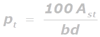
Now we have to calculate the resistance force which the stirrups will offer. We denote it as Vus. In the following fig.13.46, we can see that some of the stirrups intercept the crack.
Fig.13.46
Stirrups intercepting the crack
So these stirrups will be under tension, as they have to keep the concrete on either sides of the crack together. At the point of impending failure, ie., at the ultimate state, the stress in each of these bars will be equal to 0.87fy . So if the area of cross section of one stirrup is equal to Asv, the force in each stirrup is given by:
Note that here Asv is the area of all the legs of a single stirrup. For example, Asv of a 2-legged stirrup of 8mm dia. Will be given by:

Eq.13.35 gives the force in one stirrup. So if the number of stirrups intercepting the crack is n, then the total force is given by:
Eq.13.36: Total force = n x 0.87fy Asv
So we have to find out the value of n. This can be done based on the following fig.13.47:
Fig.13.47
No. of stirrups intercepting the crack

In the fig., p is the horizontal projection of the length of the crack, and Sv is the spacing of stirrups. Then the number of bars within a length of p is given by:
Eq.13.37: n = p /Sv
The code uses an idealization of the above fig.13.47, in which
• The crack is assumed to be straight
• The inclination of the crack with the horizontal is 45o
• The crack extends over the full depth of the beam
This is shown in the next fig.13.48 below:
Fig.13.48
Idealized conditions

In the fig., as the inclination of the crack is equal to 45o, horizontal projection will be same as the vertical projection which is equal to d (as in a 45o triangle). So Eq.13.37 becomes
Eq.13.38: n = p /Sv. So we can replace n in the Eq.13.36 and write it in the following form:
Eq.13.39:

This is the same equation given in cl.40.4 of the code.
Vertical stirrups are the ones which are most commonly used in practice. When we use a smaller diameter bar for making stirrups, the spacing required will be small. Similarly, when a larger diameter is used, the spacing required will also be higher. It is better to go for the first option. This is because closer spaced stirrups will give better crack control. The diameter of 8, 10 or 12 mm is generally used.
In the next section, we will discuss about 'inclined stirrups'.
No comments:
Post a Comment