In the previous section we saw the six stresses acting on a particle. We will try to make a mathematical formulation of the effect of the stresses.
As a result of the combined action of the six stresses, two planes known as the 'Major principal plane' and 'Minor principal plane', will be formed inside the particle. We will see the various features of these planes. The major principal plane (let us name it PQ,) is shown as a magenta coloured line in fig.13.9 below:
Major Principal plane PQ

The plane PQ divides the particle into two parts. The stress acting perpendicular to the plane (denoted here as f1 ) is shown to be tensile in nature. So f1 tries to separate the two parts away from each other.
The magnitude of f1 is given by Eq.13.5 below:
Eq.13.5:
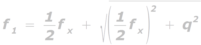
Now we want the direction of this plane. From the lessons on Strength of Materials, we know the formula for calculating the angle α that PQ makes with the vertical. This is given as Eq.13.6 below. The angle α is shown clearly in fig.13.10 below.
Eq.13.6:
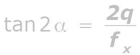
Fig.13.10 :
Direction of plane PQ

Note that in the fig., α is being measured in a clockwise direction from the vertical plane. Knowing the direction of Plane PQ, the direction of stress f1 can be easily visualized because, f1 is perpendicular to PQ.
Now we will see the minor principal plane. This plane (let us name it RS) is shown in fig.13.11 below:
Fig.13.11:
Minor Principal plane RS

The plane RS divides the particle into two parts, and the stress (denoted here as f2) is shown to be compressive in nature. So f2 tries to crush the two parts against each other.
The magnitude of f2 is given by Eq.13.7 below:
Eq.13.7:

Now we want the direction of RS. Let us consider Eq.13.6 which we saw above. The 'variable' in the equation is 2α. So when we solve it we will be getting the value of 2α. But from basic trigonometry classes, we know that there is also another value which satisfies the equation, and this value is : 2α + 180. So:
• Dividing the solution 2α by 2, we will get α
• Dividing the solution 2α + 180 by 2, we will get α + 90
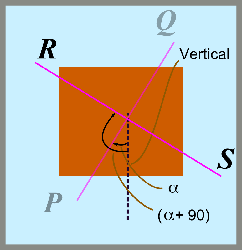
Thus we can say that the two planes are at right angles to each other. This is shown in fig.13.12 below:
Fig.13.12:
Direction of plane RS
So we get
Eq.13.8:
The angle that RS makes with the vertical is α + 90
Just as we saw in the case of PQ, knowing the direction of Plane RS, the direction of stress f2 can be easily visualized because, f2 is perpendicular to RS.
[It may be noted that though the stress acting on PQ is shown to be tensile, and that on RS is shown to be compressive in the above figures, the exact nature on an actual structure, will be finalised when we get the value of the stresses using equations 13.5, and 13.7. The sign of the quantities derived using these equations will determine the nature of the stresses.]
We now know how to calculate the stresses and their directions on the particles situated at various parts of the body of the beam. But when we consider the particles situated in the NA, there is a difference. We will discuss about it in the next section.
Copyright ©2015 limitstatelessons.blogspot.com - All Rights Reserved
No comments:
Post a Comment