In the previous section we saw the code provisions regarding spacing of stirrups, and the maximum allowable ultimate shear resistance. In this section we will discuss about the 'critical sections for shear design'.
Critical sections for shear design
We know that the shear force applied on the structure is not uniform. It is usually greatest near the supports, and decreases as we move away from the supports. If a beam carries a number of concentrated loads, the shear force is high at the region in between the support and the first concentrated load. We must have a thorough knowledge about selecting the section at which the investigation about the shear force will be made. We must select those sections at which the shear force is the greatest and/or cross sectional area is minimum. Cl.22.6.2 of the code gives us some guidelines for selecting the critical sections in various types of structures. We will now discuss each one of them in detail.Case 1
Consider a slab supported on two masonry walls and a cross beam as shown in the fig. 13.62 below:
Fig.13.62
Slab supported on masonry walls and a cross beam
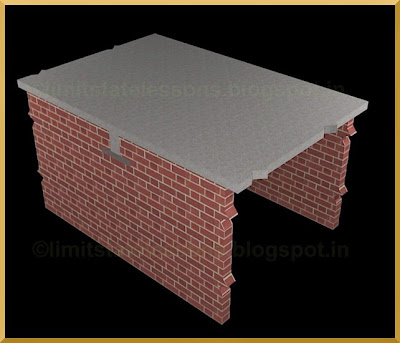
We can note the following points:
• The slab will be carrying loads on the entire area of it’s top surface. That is, loads will be present not only on the clear span area, but also on the area directly above the supporting masonry walls.
• Because of this, the cross beam will also be carrying loads not only on it’s the clear span length, but also on the portion directly above the supporting masonry walls. This is shown in the next fig.13.63:
Fig.13.63
Loads present directly above the support

• So at the portion above the supporting masonry walls, the beam will experience a force from the top due to the applied loads, and a force from the bottom due to the reaction from the supports.
• Thus these regions of the beam at the supports will be experiencing some compression.
• Because of this compressive force, the shear strength of the region will be enhanced.
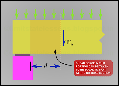
So the diagonal crack in such cases will be formed at some distance away from the face of the support. These cracks should have developed near the face of the support, as the shear force is maximum there. But the presence of the compressive forces, alters the situation. The code tells us to take a section located at a distance of d (effective depth of the beam) from the face of the support as the critical section. This is shown in the fig.13.64 below:
Fig.13.64
Critical section

This case is given in the cl.22.6.2.1 of the code. We know that the portion between the face of the support and this critical section will be subjected to a greater shear force than the shear force at the critical section. But the code allows us to use the lesser shear value at the critical section in this portion also. This is shown in the next fig.13.65 below:
Fig.13.65
Portion between the face of the support and critical section
Case 2
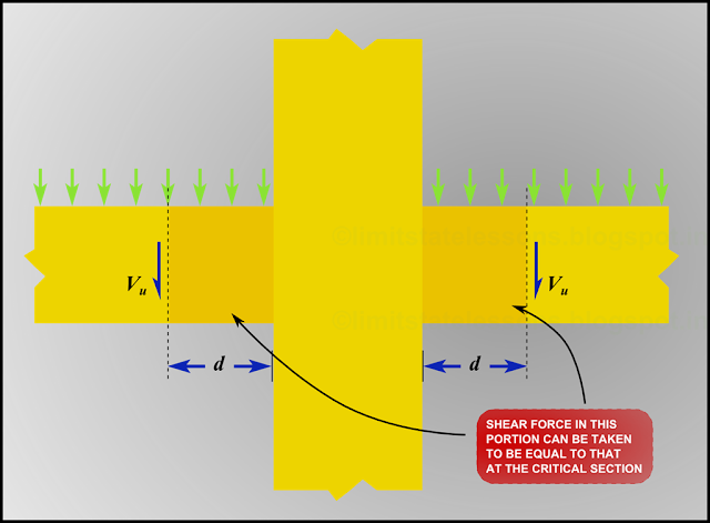
Here we consider a framed structure. We saw the 3D view of a framed structure in Chapter 9 – Analysis of singly reinforced Flanged sections. The 3D view is given in the slide 2 of the presentation given at the beginning of that chapter. The framed structure consists of columns, beams and slabs. For analysis of a framed structure, we consider 2D frames consisting of columns and beams. Such a 2D frame is shown in the slides 7 and 8 of the presentation. A portion of such a frame is shown in the fig.13.66 below:
Fig.13.66
View of a column and beam

Just as in the previous case 1,
• The portion of the beam inside the column, will be experiencing a compressive force due to the downward load from the top column, and the reaction from the bottom column.
• So the shear strength of the beam in the support portion will be enhanced.
Thus the code allows us to take the critical section at a distance d from the face of the support. This is shown in the fig.13.67 below:
Fig.13.67
Critical section in the case of framed structure

Also as in the previous case, the portion within the distance d need to be designed only for the shear force at the critical section. This is shown in the fig.13.68 below:
Fig.13.68
Portion between the face of the support and critical section
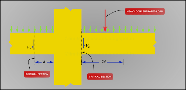
Case 3
This is a special case within case 2. In this, a heavy concentrated load is applied within a distance of two times d from the face of the support. In the presence of such a heavy concentrated load, the face of the support itself should be taken as the critical section as shown in fig.13.69 below:
Fig.13.69
Critical section when a heavy concentrated load is present within a distance of 2d
In the next section we will continue our discussion on critical sections.
Thanks,it was really helpful.
ReplyDelete