In the previous section we tabulated the values of α in Table 13.6. Every point in this table has some 'symmetric counterparts'. The table below is the same table with four such points marked as A,B,C and D.
Table 13.7:
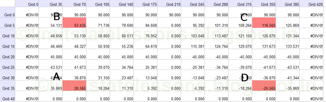
Though the angles at these four points appear to be different, we will soon see that they are closely related to each other.
First we take the particle 'A' at (grid lines 35,70)
• From table 13.2, fx = 0.505 N/mm2 • From table 13.3. q = 0.337 N/mm2
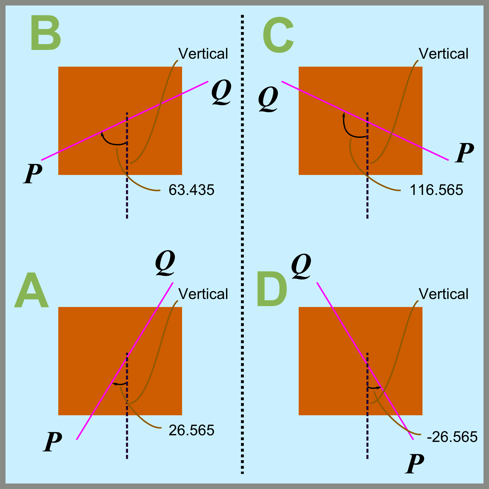
Substituting the above values in Eq.13.6 we get 2α = 0.928 radians. So α = 0.928/2 =0.464 radians, which is equal to 26.565o.
Now take the corresponding particle 'B' above NA. That is, the particle at (5,70).
• From table 13.2, fx = -0.505 N/mm2 • From table 13.3. q = 0.337 N/mm2
Substituting the above values in q.13.6 we get 2α = -0.928 radians. So α is equal to -0.464 radians, which is equal to -26.565o degrees. This is the direction of the major principal plane of a particle situated above the NA. Above the NA, The major principal plane will be carrying compressive stresses. We are interested in the planes carrying tensile stresses. So above the NA, we want the direction of the minor principal plane. We have seen earlier that the minor principal plane is at right angles to the major principal plane. So it's direction is obtained by adding 90 to α. Thus we get 90 + (-26.565) = 63.435o.
Now take the corresponding particle 'C' on the other side of the midpoint of the beam. That is, the particle at (5,350).
• From Table.13.2, fx =-0.505 N/mm2 • From Table.13.3, q =-0.337 N/mm2
Substituting the above values in Eq.13.6 we get 2α = 0.928 radians. So α = 0.464 radians, = 26.565o. As in the previous case, this is the direction of the major principal plane of a particle situated above the NA. Above the NA, The major principal plane will be carrying compressive stresses. We are interested in the planes carrying tensile stresses. So above the NA, we want the direction of the minor principal plane. We have seen earlier that the minor principal plane is at right angles to the major principal plane. So it's direction is obtained by adding 90 to α. Thus we get 90 + (+26.565) = 116.565o.
Now take the last corresponding particle 'D' below the NA. That is, the particle at (35,350).
• From Table.13.2, fx =0.505 N/mm2 • From Table.13.3, q = -0.337 N/mm2
Substituting the above values in Eq.13.6 we get 2α =-0.928 radians. So α = -0.464 radians =-26.565o. Here the particle is below the NA. ie., in the tension zone. So the angle obtained itself is the angle of the tension plane.
We can see that the direction of planes on the opposite side of the midpoint of the beam span, are mirror images. This can be shown as in fig.13.19 below:
Fig.13.19:
The following points can be noted from the above table:
• The values are mirror images about the Grid 210, as this grid line marks the midpoint of the beam.
• The values are not symmetrical about the Grid 20 grid line which marks the NA.
Another important point can also be noted from the above Table.13.7:Imagine that we are standing on the particle which is at the lowest tension fibre, and at the exact midpoint of the span of the beam. That is., the particle that we are standing on, is at the intersection of horizontal grid line 40, and vertical grid line 210. If from here, we start moving towards the left support A, and at the same time towards the topmost compression fibre, we can see that the angle of the planes increases from zero degrees. It will increase to 45o at the NA, and will further increase to 90o at the top most compression fibre. This can be demonstrated as in the animation in the following fig.13.20. In the fig., the double headed arrow shows the direction of the tensile stress. The small line perpendicular to the double headed arrow indicates the plane.
Fig.13.20 :
variation of the inclination of the plane with the vertical

We divided our beam horizontally into 12 equal parts and vertically into 8 equal parts. So we considered only a limited number of particles. If we take a larger number of particles, we will get the inclination of the plane on particles closer to each other, and we will get a smooth curve showing the above variation from zero degrees to 90 degrees. The shape of this curve will be as shown in fig.13.21 below:
Fig.13.21:
Curve showing the variation

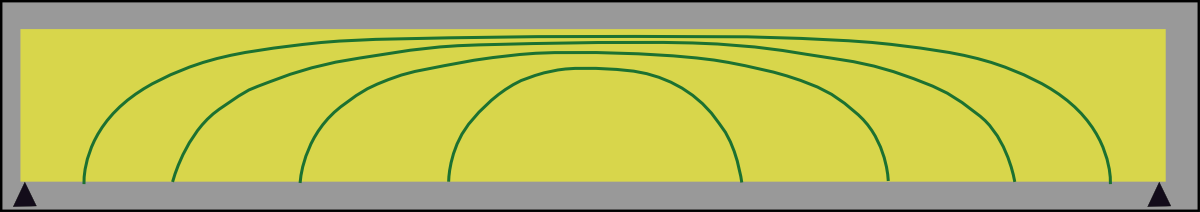
In the above fig., a curve coloured in red is shown. If we select any point on this curve, the direction of the principal tensile stress acting on the particle at that point will be tangential to the curve at that point. So, the principal plane at that point will be perpendicular to the direction of the stress. This curve is known as the 'Principal stress trajectory'. The stress trajectories of the whole beam can be shown as in fig.13.22 below:
Tensile stress trajectories for the whole beam

It can be seen that:
• If we draw a perpendicular to any of these curves at the 'level of the NA', it will be making an angle of 45o with the vertical. But this perpendicular is the direction of the principal plane at that point. So, we can say that, the principal plane is at an angle of 45o at the level of the NA. This is the same angle that we would expect based on fig.13.14.
• Each of the above curves meet the top surface at right angles.
The compression stress trajectories will be a mirror image about the NA, and can be shown as in fig.13.23 below:
Fig.13.23:
Compressive stress trajectories for the whole beam
[It may be noted that though we are showing the stress trajectories as curves in the drawings, in a real beam,they are actually surfaces.] We can see that both tensile and compressive stresses exist on all parts of the body of a beam. In these, compressive stresses do not cause much concern in a concrete beam because concrete has good strength in compression. We have to consider compressive stresses shown in fig.13.23, in some special beams such as Deep beams and beams carrying very heavy loads only. But tensile stresses have to be considered in all beams. Also recall that the stresses are maximum at the neutral axis. Among the maximum values at the Neutral axis, the ones nearer to the supports have the greater magnitudes. This we saw when we tabulated Tables 13.4 and 13.5. In the next section, we discuss how the above discussion can be applied to a reinforced concrete beam.
Copyright ©2015 limitstatelessons.blogspot.com - All Rights Reserved
One of the best sites for getting in-depth view of this subject
ReplyDeleteCommendable effort ,