In
the previous section we saw the steps required to complete the design part. In this section we will see the rules that we have to follow while arranging the steel inside the beam.
Where Φ is the diameter of the main bar and Φl is the diameter of the links. This equation is applicable when the bottom bars contain only 3 bars and all of them are of the same diameter.
Fig.4.12
Bars of a beam placed in layers
 Fig.4.13
Bundles of bars in a beam

A brief description about bundled bars and 'Equivalent diameter' can be seen here.
In the next section we will discuss about the minimum and maximum areas of tension steel in beams.
Minimum spacing that should be provided between the bars of a beam
The
clear space provided between parallel reinforcing bars should not be
less than the minimum value specified in cl 26.3.2 of the code.
For
a beam, the minimum spacing specified by the code is shown in fig
4.10 below:
Fig.4.10
Minimum horizontal spacing between bars

Fig.4.10
Minimum horizontal spacing between bars

Fig.4.10(a) shows the case when the all the bottom bars of the beam are
of the same diameter. Fig.4.10(b) shows the case when bars of
different diameters are used in the bottom layer.
Based on fig.4.10(a), we can write an equation to quickly calculate Sh:
Eq.4.12
Sh = [b-(2Cc +2Φl +3Φ)] /2
Based on fig.4.10(a), we can write an equation to quickly calculate Sh:
Eq.4.12
Sh = [b-(2Cc +2Φl +3Φ)] /2
Where Φ is the diameter of the main bar and Φl is the diameter of the links. This equation is applicable when the bottom bars contain only 3 bars and all of them are of the same diameter.
If in the fig., the middle bar is of a different diameter, the eq. can be written as:
Eq.4.13
Sh = [b-(2Cc +2Φl +2Φ1 +Φ2)] /2
Where Φ1 is the diameter of the two edge bars and Φ2 is the diameter of the middle bar.
By providing a spacing greater than this minimum spacing, we can ensure that concrete is placed uniformly in between and around the bars and can be compacted well during the placement of fresh concrete.
In
general, the slabs require a low percentage of flexural
reinforcement. That is., when we take a 1m width of a slab of thickness Dm, the area of
cross section of the slab will be 1 xD =D m2, and
only a lesser percentage of this D m2 is required as the area of
tension steel Ast. So there will be sufficient space to provide the
required steel in one layer. And there will be no need to reduce the spacing between
the bars to values which are below the minimum required values specified. But the beams will be
having a limited width, and require relatively higher percentage of
flexural reinforcement. So when we arrange the bars by giving the
required minimum spacing Sh between the bars and the clear cover Cc required on the two sides, the total space required may exceed the
width of the beam. Fig.4.11 shows such an example:
Fig.4.11
Insufficient width of a beam
 In the fig.4.11, let Dia. Φ of all the four bars in the bottom layer = 20mm; Dia of links Φl = 10mm; Cc = 30mm; Size of aggegate = 20mm. Then Sh = larger of {20} and {20 +5} = 25mm. So the total width of beam required =
2Cc + 2Φl + 4Φ +3Sh = 235mm
But the total width available is only 200mm. In such a situation, the following options can be considered:
• Increase
the beam widthFig.4.11
Insufficient width of a beam

2Cc + 2Φl + 4Φ +3Sh = 235mm
But the total width available is only 200mm. In such a situation, the following options can be considered:
• Place
the bars in two or more layers with the minimum required spacing
between layers as shown in the fig.4.12
• Bundle groups of parallel bars as shown in fig.4.13. Each bundle can have two, three or four bars
• Bundle groups of parallel bars as shown in fig.4.13. Each bundle can have two, three or four bars
Fig.4.12
Bars of a beam placed in layers

Bundles of bars in a beam
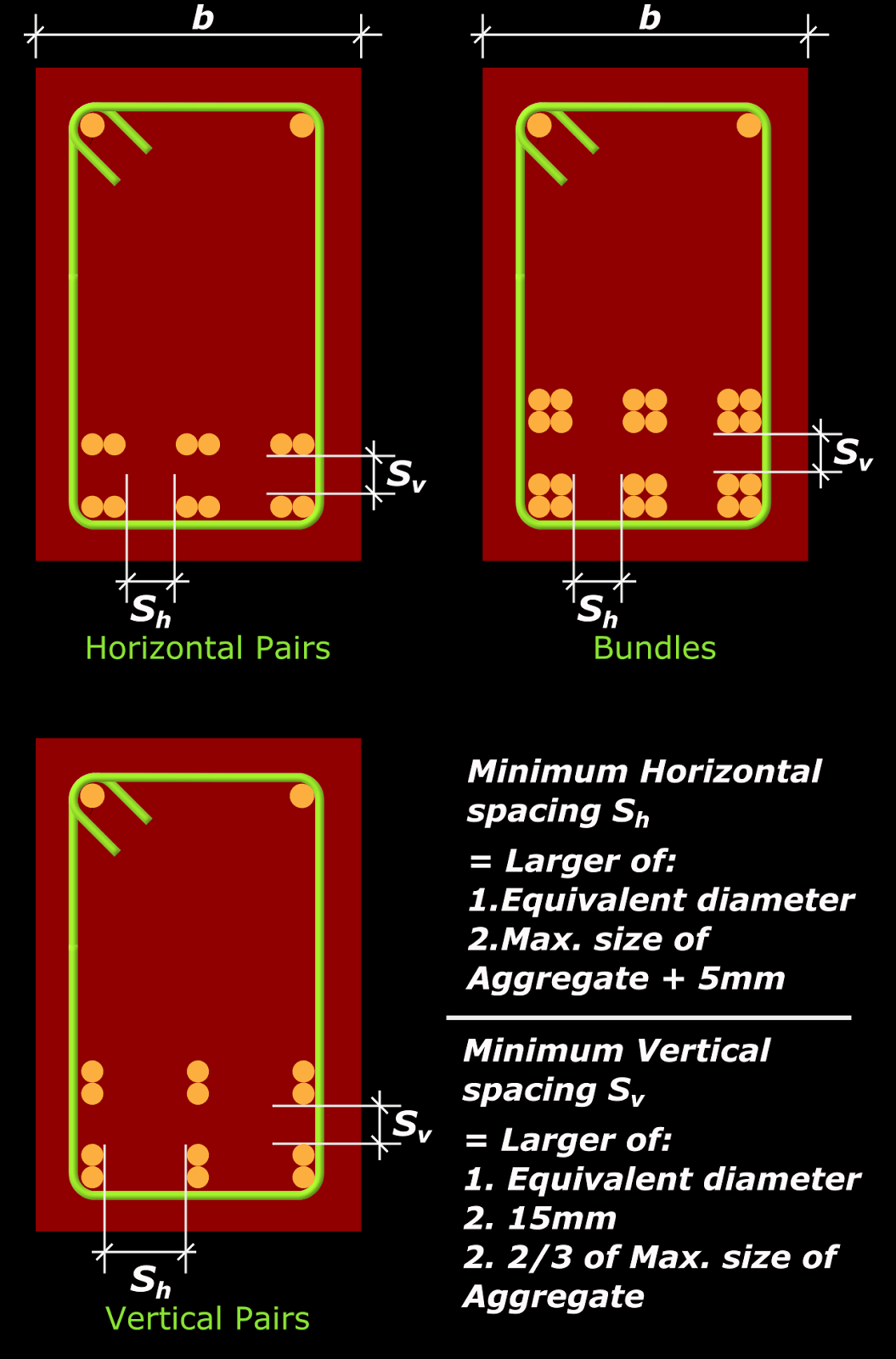
A brief description about bundled bars and 'Equivalent diameter' can be seen here.
Maximum Spacing allowable between bars of a beam.
The clear space provided between parallel reinforcing bars should not be greater than the maximum value specified by the code. (cl 26.3.3). In the case of beams, we get the maximum allowable values from table 15 of the code. This table gives the clear distance between the parallel reinforcement bars or groups near the tension face of the beam. The clear distance that we provide between the bars should not exceed these values. By providing a clear distance lesser than the allowable values, we can ensure that the crack widths will be minimum and also that there is sufficient bond between the bars and concrete.In the next section we will discuss about the minimum and maximum areas of tension steel in beams.
Thanks honor to share u
ReplyDeleteThanks for the valuble post, keep more post
ReplyDeleteBest tmt bars in tamilnadu
Very valuable post TMT bar manufacturers in Tamilnadu, TMT bar Dealers in Tamilnadu, and TMT bar suppliers in Tamilnadu, corrosion resistance TMT bars.
ReplyDeleteThank you for sharing this valuable post. The information you provided is informative and helpful. If you want learn more about Best TMT Bar in India then you can visit the website.
ReplyDeleteThanks for sharing informative blog article with us. Please keep updating us with this valuable post. Best TMT Bars in West Bengal
ReplyDeleteMahan Tmt 550D the Top 10 Best Tmt in Bihar: A Complete Guide to the Best Choices
ReplyDeleteMahan TMT 550D is among the top 10 best TMT in Bihar. It is known for its high quality and ability to provide strength and durability. This guide Will help you choose the right TMT bar for your construction project in Bihar.
Know More:- Visit mahantmt.com!
Best TMT Bar Manufacturer and Supplier in Bihar 2023
ReplyDeleteMahan TMT 550D is the best TMT bar that you can buy in Bihar in 2023. It is made by Magadh Industries, a leading steel manufacturer in the state. Mahan TMT 550D is made using state-of-the-art technology, which gives it superior strength, durability, and weldability.
Mahan TMT 550D is available in a wide range of diameters, so you can find the perfect size for your construction project. It is also backed by a strong customer support team, which is available to help you with any questions or problems you may have.
Best TMT in Bihar, Mahan TMT price today, Magadh TMT price today
Know More:- Visit Mahantmt.com!