In
the previous section we saw the type of beam in which the steel reinforcement yielded before the ultimate state was reached. In this section we are going to discuss another type of beam. This beam has a larger area of steel and/or the steel is of high strength grade. Let us see the various stages before failure:
Stage 1: C and T increases normally to resist the external load. The stresses and strains are in the linear elastic state. This is shown in the fig.3.23 below. The strain in steel at this stage is denoted as εst,1. This is less than ε*st .
In the stage 1, εst,1 < ε*st , because the steel has not yielded. It is in the initial linear elastic state. Also εc,1 the strain in concrete is far less than 0.0035, the ultimate strain. The stress fst,1 in steel is less than 0.87fy . We know that 0.87fy is the design yield stress (fy/1.15 = 0.87fy). That is., the stress corresponding to the strain ε*st.
The stress fc,1 in the top most compression fibre is far less than 0.447fck , the ultimate stress in concrete.
We can see that this stage 1 is same as the stage 1 of the previous beam. (fig.3.22 of previous section)
Fig.3.23
Stages before failure of a beam section
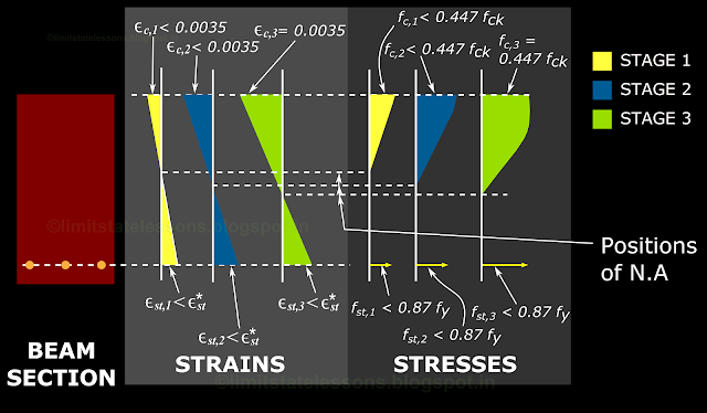
Stage 2: As we continue to increase the load, the steel will not yield because now it has a larger area and/or the steel is of high strength grade, and so is stronger. The situation of having 'larger area' can be viewed mathematically as follows: Tensile stress = Tensile force / Area of steel. As the area which is in the denominator has increased, the tensile stress has decreased. So the steel does not yield. The situation of having steel of high strength grade is obvious: As the steel itself is strong, very large force is required to make it yield. In the previous beam, in stage 2, the steel yielded and entered the horizontal flat portion of the stress strain curve . So in it, the steel elongated under constant force. But here, steel has not reached the flat portion.
So when the loading increases, the tensile force in steel also increases. To maintain the equilibrium, the compressive force C has to increase in such a way that C = T. For this, the NA shifts downwards to increase the area of the region under compression, and thus to increase C.
These details can be seen in the fig.3.23 above. In the stage 2, the strain εst,2 in steel is still less than ε*st . So the steel has not yielded. The NA has shifted downwards. The strain εc,2 in the top most compression fibre is still less than 0.0035.
The stress fst,2 in steel is less than the design yield strength of 0.87fy, indicating that the stress is still capable of increasing. The stress in concrete fc,2 is less than 0.447fck.
So the section manages to resist the increased external bending moment by shifting the NA downwards. But as part of the experiment, we are increasing the load further. So the beam moves on to the next stage.
Stage 3: We are increasing the load further. During this increase also, the steel does not yield. It continues to increase the T in it. C also has to increase. The increase in area of concrete (by shifting the NA downwards) becomes insufficient to take this higher C. So the stress in it will increase and so will the strain. The strain will reach the ultimate value of 0.0035. Thus the impending state of failure is reached. With any more increase in load, the concrete will fail by crushing. At this point also, the steel is safe.
In the previous beam also, the failure was by crushing of concrete. But there is an important difference. In the present beam, the steel has not yielded. So there was no deflection for the beam and there were no wider cracks. So there was no warning about failure. This type of failure occurs suddenly and is called compression failure.
The details of stage 3 are shown in the fig.3.23 above. In the stage 3, the strain εst,3 in steel is still less than ε*st . That is., the steel is showing no sign of yielding. The NA has shifted further downwards. The strain εc,3 in the top most compression fibre has reached 0.0035, which is the ultimate strain.
The stress fst,3 in steel is still less than 0.87fy. The stress in concrete fc,3 has reached 0.447fck.
It may be noted that in the above experiment on the second beam, we say that the beam has reached the ultimate state (the state of impending failure), when the strain in the top most compression fibre reached 0.0035. At this point, the steel is nowhere near the point of yielding. But as the concrete has reached the ultimate state, the beam as a whole has reached the ultimate state.
The beam shown in fig.3.20 of the previous section is an example of this type of beam. In it, the stress and strain at the ultimate state is in the blue colored curved region.
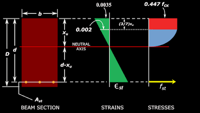
Now we can discuss a point about attaching the stress-strain curve of steel in the beam sections. We have seen that we just need one single stress value from the stress-strain curve of steel: That which corresponds to the centroid. Any other point on the curve is irrelevant to a particular problem. So the curve is usually not shown in the analysis diagrams. Instead, an arrow is shown at the level of the centroid to indicate the stress. But we have to attach the stress-strain curve of concrete because it's dimensions like total depth, depth of rectangular portion etc., has to be calculated for the determination of compressive forces. An example is shown in the fig.3.24 below:
Fig.3.24
Stresses and strains at ultimate state
We can say that the beam in the first experiment above has a particular combination of steel:
Combination 1 is such that at ultimate state, the steel would have yielded. That is., during the loading process, the steel yields first, and as the loading is continued, the top most compression fibre reaches the ultimate state. Such a beam is called an 'Under reinforced beam'.
Combination 2 is such that at ultimate state, the steel would not have yielded. That is., during the loading process, the top most compression fibre reaches the ultimate state first. The steel will still be in the elastic state. There is no point in thinking about what will happen to steel if we continue loading after this ultimate state. This is because even though the steel is still safe, the 'beam as a whole' will cease to serve it's purpose when the top most compression fibre reaches the ultimate state. Such a beam is called an 'Over reinforced beam'.
So in both Under reinforced and Over reinforced beams, the strain of 0.0035 and a stress of 0.447fck in the top most concrete compression fibre is the criterion for Ultimate state.
In the above definitions for Under reinforced and Over reinforced sections, that of the Over reinforced section is more 'direct'. Because, the criterion for ultimate state is related to concrete, and in the Over reinforced section, that concrete reaches the ultimate state, while steel is still safe. But in the case of Under reinforced section, the criterion for ultimate state will occur only after the yielding of steel.
We can do some mathematical derivations by which, we will be able to say whether a beam section given to us is Under reinforced or Over reinforced. For this purpose, we fix up an 'ideal' combination which falls between the above two combinations. This combination is such that during the loading, the attainment of ultimate state in the topmost compression fibre and the yielding of steel happens simultaneously. Such a section is called a 'Balanced section'. In the next section we will analyze a balanced section. After that analysis, we will be able to mathematically define under reinforced and over reinforced sections.
Previous
Next
Stage 1: C and T increases normally to resist the external load. The stresses and strains are in the linear elastic state. This is shown in the fig.3.23 below. The strain in steel at this stage is denoted as εst,1. This is less than ε*st .
In the stage 1, εst,1 < ε*st , because the steel has not yielded. It is in the initial linear elastic state. Also εc,1 the strain in concrete is far less than 0.0035, the ultimate strain. The stress fst,1 in steel is less than 0.87fy . We know that 0.87fy is the design yield stress (fy/1.15 = 0.87fy). That is., the stress corresponding to the strain ε*st.
The stress fc,1 in the top most compression fibre is far less than 0.447fck , the ultimate stress in concrete.
We can see that this stage 1 is same as the stage 1 of the previous beam. (fig.3.22 of previous section)
Fig.3.23
Stages before failure of a beam section
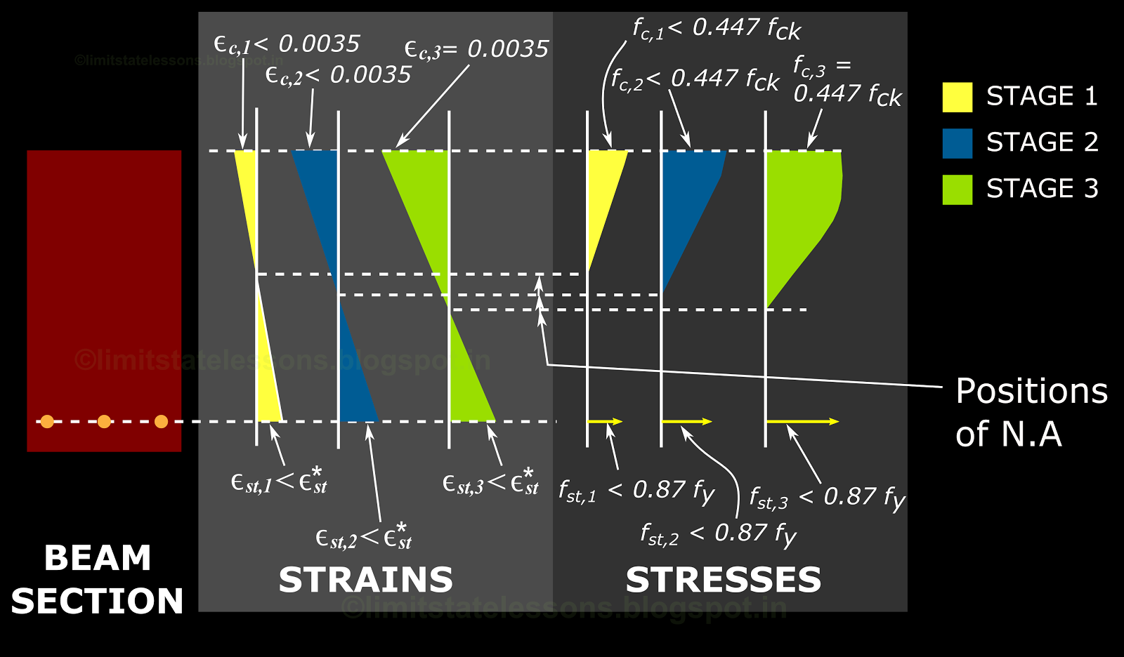
Stage 2: As we continue to increase the load, the steel will not yield because now it has a larger area and/or the steel is of high strength grade, and so is stronger. The situation of having 'larger area' can be viewed mathematically as follows: Tensile stress = Tensile force / Area of steel. As the area which is in the denominator has increased, the tensile stress has decreased. So the steel does not yield. The situation of having steel of high strength grade is obvious: As the steel itself is strong, very large force is required to make it yield. In the previous beam, in stage 2, the steel yielded and entered the horizontal flat portion of the stress strain curve . So in it, the steel elongated under constant force. But here, steel has not reached the flat portion.
So when the loading increases, the tensile force in steel also increases. To maintain the equilibrium, the compressive force C has to increase in such a way that C = T. For this, the NA shifts downwards to increase the area of the region under compression, and thus to increase C.
These details can be seen in the fig.3.23 above. In the stage 2, the strain εst,2 in steel is still less than ε*st . So the steel has not yielded. The NA has shifted downwards. The strain εc,2 in the top most compression fibre is still less than 0.0035.
The stress fst,2 in steel is less than the design yield strength of 0.87fy, indicating that the stress is still capable of increasing. The stress in concrete fc,2 is less than 0.447fck.
So the section manages to resist the increased external bending moment by shifting the NA downwards. But as part of the experiment, we are increasing the load further. So the beam moves on to the next stage.
Stage 3: We are increasing the load further. During this increase also, the steel does not yield. It continues to increase the T in it. C also has to increase. The increase in area of concrete (by shifting the NA downwards) becomes insufficient to take this higher C. So the stress in it will increase and so will the strain. The strain will reach the ultimate value of 0.0035. Thus the impending state of failure is reached. With any more increase in load, the concrete will fail by crushing. At this point also, the steel is safe.
In the previous beam also, the failure was by crushing of concrete. But there is an important difference. In the present beam, the steel has not yielded. So there was no deflection for the beam and there were no wider cracks. So there was no warning about failure. This type of failure occurs suddenly and is called compression failure.
The details of stage 3 are shown in the fig.3.23 above. In the stage 3, the strain εst,3 in steel is still less than ε*st . That is., the steel is showing no sign of yielding. The NA has shifted further downwards. The strain εc,3 in the top most compression fibre has reached 0.0035, which is the ultimate strain.
The stress fst,3 in steel is still less than 0.87fy. The stress in concrete fc,3 has reached 0.447fck.
It may be noted that in the above experiment on the second beam, we say that the beam has reached the ultimate state (the state of impending failure), when the strain in the top most compression fibre reached 0.0035. At this point, the steel is nowhere near the point of yielding. But as the concrete has reached the ultimate state, the beam as a whole has reached the ultimate state.
The beam shown in fig.3.20 of the previous section is an example of this type of beam. In it, the stress and strain at the ultimate state is in the blue colored curved region.
Thus we now know the reason why, at the ultimate state, different values
are possible for the stress in steel, while that in the extreme
concrete fibre remain fixed at 0.447fck.
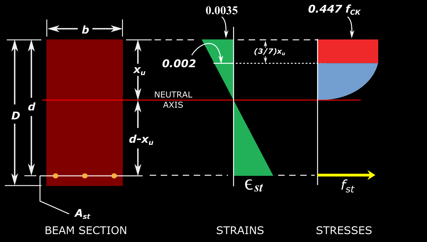
Now we can discuss a point about attaching the stress-strain curve of steel in the beam sections. We have seen that we just need one single stress value from the stress-strain curve of steel: That which corresponds to the centroid. Any other point on the curve is irrelevant to a particular problem. So the curve is usually not shown in the analysis diagrams. Instead, an arrow is shown at the level of the centroid to indicate the stress. But we have to attach the stress-strain curve of concrete because it's dimensions like total depth, depth of rectangular portion etc., has to be calculated for the determination of compressive forces. An example is shown in the fig.3.24 below:
Fig.3.24
Stresses and strains at ultimate state
We can say that the beam in the first experiment above has a particular combination of steel:
A combination
of:
• a particular grade of steel fy,1
(Fe250, 415 or 500.) and
• area of steel Ast,1 .
Similarly, the beam in the second experiment has a
combination of fy,2 and Ast,2. The cross sectional dimensions: depth and
width, of both the beams are the same.
Combination 1 is such that at ultimate state, the steel would have yielded. That is., during the loading process, the steel yields first, and as the loading is continued, the top most compression fibre reaches the ultimate state. Such a beam is called an 'Under reinforced beam'.
Combination 2 is such that at ultimate state, the steel would not have yielded. That is., during the loading process, the top most compression fibre reaches the ultimate state first. The steel will still be in the elastic state. There is no point in thinking about what will happen to steel if we continue loading after this ultimate state. This is because even though the steel is still safe, the 'beam as a whole' will cease to serve it's purpose when the top most compression fibre reaches the ultimate state. Such a beam is called an 'Over reinforced beam'.
So in both Under reinforced and Over reinforced beams, the strain of 0.0035 and a stress of 0.447fck in the top most concrete compression fibre is the criterion for Ultimate state.
In the above definitions for Under reinforced and Over reinforced sections, that of the Over reinforced section is more 'direct'. Because, the criterion for ultimate state is related to concrete, and in the Over reinforced section, that concrete reaches the ultimate state, while steel is still safe. But in the case of Under reinforced section, the criterion for ultimate state will occur only after the yielding of steel.
So
one may think that the loading can be continued even after the
yielding of steel because the concrete is still safe. But this is not
the case. The attainment of ultimate state in the concrete is related
to the quantity of steel that is provided. This can be proved as
follows:
We
have seen that when the steel yields at constant stress, the NA moves
upwards to increase the lever arm z. (fig.3.22) Lesser area of steel
means that the steel yields at lower loads, and so the NA will also
move upwards at these lower loads. So the area of concrete available
becomes less, and thus it will reach the ultimate state even at lower
loads.
So
we cannot say that if low quantity of steel is provided, the steel
will become unsafe at lower loads, and concrete will remain safe. The
fact is that at low quantity steel, concrete will reach ultimate
state at lower loads. However, we must remember that when we design a
new beam, all provisions of the various relevant codes should be
satisfied, and lower quantities of steel than required should not be
permitted.
We can do some mathematical derivations by which, we will be able to say whether a beam section given to us is Under reinforced or Over reinforced. For this purpose, we fix up an 'ideal' combination which falls between the above two combinations. This combination is such that during the loading, the attainment of ultimate state in the topmost compression fibre and the yielding of steel happens simultaneously. Such a section is called a 'Balanced section'. In the next section we will analyze a balanced section. After that analysis, we will be able to mathematically define under reinforced and over reinforced sections.
Previous
Next
Copyright ©2015 limitstatelessons.blogspot.com- All Rights Reserved
No comments:
Post a Comment