In
the previous section we saw the method to fix up the depth of the beam. Now we will see how to fix up the width b. For
this, we can consider the following aspects: If the beam has to
support a masonry wall, it is better to give a width in such a way
that the sides of the beam are flush with the finished surface of the
wall. This will generally lead us to give a width of 200 mm or 230mm
for the beam. This is because masonry walls are generally 200 or 230 mm thick. An example for this is shown in the fig. 4.3 below:
Fig.4.3
Beam supporting a masonry wall

In the above fig., the finished surface of the walls is shown. At the time of making the formworks for the beam, we must consider the the thickness of finishes which will be applied on the masonry work and the concrete work. The width of the form work should be in such a way that, when all the finishes are applied, the side surfaces of the beam will be flush with the side surfaces of the wall.
If the beam that we are considering is part of a framed structure, its width should be less than or equal to the lateral dimension of the column into which it frames. This generally leads us to give widths of 200 mm,250 mm, 300 mm etc., An example is shown in the fig.4.4 below:
Fig.4.4
Beam framing into a column

Also we have to consider the availability of formworks. Usually, formworks are made in such a way that their widths are kept equal to the width of beams commonly adopted in the locality. This will fecilitate their re-usability.
Thus we can fix up the preliminary depth and width of a beam. So the self wt. can be calculated and the analysis and design can be carried out. After the design is complete, various checks have to be done to make sure that the designed beam is capable to resist all the load effects acting upon it. If it is found that the beam designed with these preliminary dimensions do not have adequate strength, new improved dimensions should be given, and the analysis and design should be done again.
After designing the beam, when the checks are being done, the following scenario can arise: The dimensions are found to be unsatisfactory. Either the width or depth or both has to be increased. In such a case, if we are free to increase width and depth, we must opt to increase the depth. This will increase the moment resisting capacity and also will increase the stiffness against bending. So there will be lesser deflections, curvatures and crack widths. But very deep beams are undesirable because they lead to loss of headroom or an increase in the overall height of the building.
4.2: In general, the recommended ratio of overall depth to width (D/b) is in the range 1.5 to 2. But it can go up to 3 or even more for beams carrying very heavy loads such as bridge girders.
Widths and depths are also governed by the shear force at the section. We will discuss about it when we take up the topic of shear design.
If the slab which is to be supported over a beam is cast integrally with the beam, it can be modelled as a flanged beam. This will also give a higher strength to the beam, details of which will be discussed in the section on T- beams and L-beams.
So now we know how to fix up the preliminary dimensions of the cross section of the beam. Before proceeding to the next step, we must do some checks related to these cross sectional dimensions.
• If l/D is less than 2 for a simply supported beam, it should be considered as a deep beam
Note
that the overall depth D
is
being used in the ratio. Deep beams are discussed in a later chapter.
4.4: We must also check whether the beam is slender or not. If the beam is too long when compared to it's lateral dimensions, chances are that the beam will fall under the category of 'slender beams'. Slender beams will have lateral instability. To check whether the beam is slender or not, we must refer the cl 23.3 of the code
According to this clause:
For a simply supported or continuous beam, the clear distance between the lateral restraints should not be greater than the lesser of the following two values:
• 60b
• 250b2⁄d
For a cantilever beam, the clear distance between free end of the cantilever to the lateral restraint should not be greater than the lesser of the following two values:
• 25b
• 100b2⁄d
In the above checks b is the width of the beam, and d is the effective depth.
So now we have three checks (4.2, 4.3 and 4.4) that should be done just after fixing up the preliminary dimensions. These checks should be done again if these preliminary dimensions are changed.
In the above check for slenderness, we find that the effective depth d is coming in the calculation. We know that when the effective depth increases, the lever arm z also increases, and so the beam will be able to give more resisting moment. So we must get the maximum d possible. We have fixed up the preliminary value for D. In this situation, the concrete cover given to the bottom bars will decide the value of d, as shown in the fig.4.5 below. In the fig., Φ is the diameter of the bottom bars.
Fig.4.5
Concrete cover and effective depth


The code also specifies concrete cover requirements based on fire resistance. This is given in cl 26.4.3 and table 16.
Thus now we know how to fix the concrete cover Cc . So we can write the equations for calculating the total depth D and effective depth d. We can write them based on the fig.4.8 below:
Fig.4.8
Details of concrete cover and effective depth

From the fig.4.8 we get
Eq.4.5: D = d + Φ/2 + Φl + Cc
and Eq.4.6: d = D - ( Φ/2 + Φl + Cc )
Where Φ is the diameter of main bars and Φl is the diameter of bars used for making the links.
Some examples demonstrating the calculation of d is given here
So now we know how to calculate the effective depth d of any beam section. But there is one more obstacle that we have to overcome in this calculation: The values of Φ and Φl are not known at the time when the preliminary dimensions are fixed. So we cannot do the check 4.4.
In this situation, we assume a value for Φ and another for Φl. The values usually assumed are 20mm for Φ and 10mm for Φl. We know the five possible values for Cc from table 4.1 above. Corresponding to each of these five values, there will be a value for the 'effective cover'. This is the cover measured from the nearest outer surface of concrete upto the center of the steel bars. So the table 4.2 can be prepared which will directly give the effective cover for each of the exposure condition. In the table, all values are in mm
Table 4.2
Sample calculation:
Let us take 'Severe' exposure condition. Then 'effective cover' = 45 +10 +20/2 = 65mm
For all the values of 'effective cover' in the above table, 20mm and 10mm are assumed. So after finalizing the beam section, the check should be done again with the actual diameters provided in the beam.
So we have the basic information required to start the design of a beam. In the next section we will see the design process.
Fig.4.3
Beam supporting a masonry wall

In the above fig., the finished surface of the walls is shown. At the time of making the formworks for the beam, we must consider the the thickness of finishes which will be applied on the masonry work and the concrete work. The width of the form work should be in such a way that, when all the finishes are applied, the side surfaces of the beam will be flush with the side surfaces of the wall.
If the beam that we are considering is part of a framed structure, its width should be less than or equal to the lateral dimension of the column into which it frames. This generally leads us to give widths of 200 mm,250 mm, 300 mm etc., An example is shown in the fig.4.4 below:
Fig.4.4
Beam framing into a column

Also we have to consider the availability of formworks. Usually, formworks are made in such a way that their widths are kept equal to the width of beams commonly adopted in the locality. This will fecilitate their re-usability.
Thus we can fix up the preliminary depth and width of a beam. So the self wt. can be calculated and the analysis and design can be carried out. After the design is complete, various checks have to be done to make sure that the designed beam is capable to resist all the load effects acting upon it. If it is found that the beam designed with these preliminary dimensions do not have adequate strength, new improved dimensions should be given, and the analysis and design should be done again.
After designing the beam, when the checks are being done, the following scenario can arise: The dimensions are found to be unsatisfactory. Either the width or depth or both has to be increased. In such a case, if we are free to increase width and depth, we must opt to increase the depth. This will increase the moment resisting capacity and also will increase the stiffness against bending. So there will be lesser deflections, curvatures and crack widths. But very deep beams are undesirable because they lead to loss of headroom or an increase in the overall height of the building.
4.2: In general, the recommended ratio of overall depth to width (D/b) is in the range 1.5 to 2. But it can go up to 3 or even more for beams carrying very heavy loads such as bridge girders.
Widths and depths are also governed by the shear force at the section. We will discuss about it when we take up the topic of shear design.
Sometimes
architectural requirements will have to be considered when deciding
upon the size of beams. It may so happen that the depth of the beam has to be kept within a certain limit. In such a situation, we can design it as a doubly reinforced section, and thus
achieve the desired strength.
High strength concrete and steel can
also be used for increasing the strength of a beam section.
If the slab which is to be supported over a beam is cast integrally with the beam, it can be modelled as a flanged beam. This will also give a higher strength to the beam, details of which will be discussed in the section on T- beams and L-beams.
So now we know how to fix up the preliminary dimensions of the cross section of the beam. Before proceeding to the next step, we must do some checks related to these cross sectional dimensions.
Check whether the beam is a deep beam.
4.3: For
this, we must calculate the ratio l/D (span to overall depth of the
beam). Then we must compare it with the values given in cl.29.1 of
the code:
• If l/D is less than 2 for a simply supported beam, it should be considered as a deep beam
• If
l/D is
less than 2.5 for a continuous beam, it should be considered as a
deep beam
Check whether the beam is a slender beam
4.4: We must also check whether the beam is slender or not. If the beam is too long when compared to it's lateral dimensions, chances are that the beam will fall under the category of 'slender beams'. Slender beams will have lateral instability. To check whether the beam is slender or not, we must refer the cl 23.3 of the code
According to this clause:
For a simply supported or continuous beam, the clear distance between the lateral restraints should not be greater than the lesser of the following two values:
• 60b
• 250b2⁄d
For a cantilever beam, the clear distance between free end of the cantilever to the lateral restraint should not be greater than the lesser of the following two values:
• 25b
• 100b2⁄d
In the above checks b is the width of the beam, and d is the effective depth.
So now we have three checks (4.2, 4.3 and 4.4) that should be done just after fixing up the preliminary dimensions. These checks should be done again if these preliminary dimensions are changed.
In the above check for slenderness, we find that the effective depth d is coming in the calculation. We know that when the effective depth increases, the lever arm z also increases, and so the beam will be able to give more resisting moment. So we must get the maximum d possible. We have fixed up the preliminary value for D. In this situation, the concrete cover given to the bottom bars will decide the value of d, as shown in the fig.4.5 below. In the fig., Φ is the diameter of the bottom bars.
Fig.4.5
Concrete cover and effective depth

So the knowledge about concrete cover is vital for calculating d. We will soon see that, the value of d is important not only for the above check for slenderness, but also for the design of the beam itself. So
we have to learn how the thickness of this concrete cover can be
fixed:
Concrete cover
When
steel bars are placed in a structural member, it will be embedded
completely in concrete. There will naturally be sufficient embedment
on the inner sides of the member. But we have to take special care
about the outer or exposed surface. For example, the bottom bars of a
beam will have enough concrete on it's top side. But there will be a
lesser concrete near the bottom and the sides. This is shown in the
fig.4.6 below. We call this thickness of concrete which covers the steel
as the 'concrete cover'.
Fig.4.6
Concrete cover

The
concrete cover serves the following purposes:
• It
gives sufficient protection to the bars from corrosion and fire.
• When
the bars are stressed by a tensile or compressive force, they tend to
move from their original positions. But this movement should be
prevented to enable the effective transfer of stresses between the
concrete and steel. By providing the required cover on all the sides
of the bar, they will be sufficiently embedded inside concrete, and
so, this movement will not occur.
The
concrete cover, usually denoted as Cc, should not fall
below the values given by the code. In the code, it is given as
'Nominal cover' in the cl. 26.4.1. We can obtain the values of Cc by
referring clauses 26.4.1 and 26.4.2 of the code. These specified
values should be given from the outer surface of the links. This is
shown in the fig.4.7 below:
Fig.4.7
Specified cover provided from outer surface of links


Based
on the requirements given in the code, we can prepare Table 4.1 below
which gives the value of Cc for various conditions.
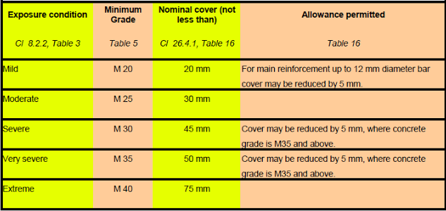
For
example,if we are to design a beam which will be subjected to
'severe' exposure conditions, the value of Cc to be provided is 45 mm
, and the minimum grade of concrete to be used is M 30 .
The
code also gives some guidelines about the changes from the specified
cover when the actual work is carried out at the site. In actual
construction, the cover provided for the bar may become different
from the values specified by the designer. The allowable tolerance
is given as Note no. 2 in Table 16 of the code. From this note, it is
clear that the cover can increase by a maximum value of 10 mm from
the value specified by the designer. But it cannot decrease (-0 mm
tolerance) from that value.
The code also specifies concrete cover requirements based on fire resistance. This is given in cl 26.4.3 and table 16.
Thus now we know how to fix the concrete cover Cc . So we can write the equations for calculating the total depth D and effective depth d. We can write them based on the fig.4.8 below:
Fig.4.8
Details of concrete cover and effective depth

From the fig.4.8 we get
Eq.4.5: D = d + Φ/2 + Φl + Cc
and Eq.4.6: d = D - ( Φ/2 + Φl + Cc )
Where Φ is the diameter of main bars and Φl is the diameter of bars used for making the links.
Some examples demonstrating the calculation of d is given here
So now we know how to calculate the effective depth d of any beam section. But there is one more obstacle that we have to overcome in this calculation: The values of Φ and Φl are not known at the time when the preliminary dimensions are fixed. So we cannot do the check 4.4.
In this situation, we assume a value for Φ and another for Φl. The values usually assumed are 20mm for Φ and 10mm for Φl. We know the five possible values for Cc from table 4.1 above. Corresponding to each of these five values, there will be a value for the 'effective cover'. This is the cover measured from the nearest outer surface of concrete upto the center of the steel bars. So the table 4.2 can be prepared which will directly give the effective cover for each of the exposure condition. In the table, all values are in mm
Table 4.2
| Exposure condition | Cc | Φ | Φl | Effective cover |
| Mild | 20 | 20 | 10 | 40 |
| Moderate | 30 | 20 | 10 | 50 |
| Severe | 45 | 20 | 10 | 65 |
| Very Severe | 50 | 20 | 10 | 70 |
| Extreme | 75 | 20 | 10 | 95 |
Let us take 'Severe' exposure condition. Then 'effective cover' = 45 +10 +20/2 = 65mm
For all the values of 'effective cover' in the above table, 20mm and 10mm are assumed. So after finalizing the beam section, the check should be done again with the actual diameters provided in the beam.
So we have the basic information required to start the design of a beam. In the next section we will see the design process.
No comments:
Post a Comment