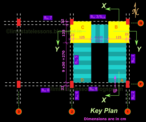
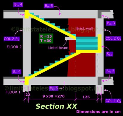
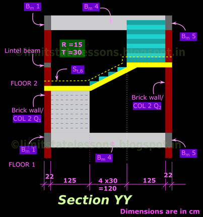
In this section we will discuss the analysis and design of an 'Open well stair'. In this type of stairs, the flights and landings used for climbing, are given near the outer walls of a stair case room. This will create a 'well-like' portion near the middle of the room. The figs.16.102,103 and 104 below shows the plans and sections of an open-well stair.
In the above figs., the method of naming of beams and columns is as specified in SP34. For example: COL 2 Q2 is the column Q2 in FLOOR 2.
From the key plan, we can see that in each floor, there are three flights. AB, BC and CD. In Floor1. the flight AB rests on the ground at A and on an inclined beam at B. This inclined beam (denoted as St,B) is supported on Col Q1 and Q2. Flight BC is supported on masonry walls at B and C. Though not related to our present stair design problem, lintel beams should be provided in all the masonry walls as shown in the section YY. In this building, the height at which landing C is embedded in the masonry wall coincides with the position of the Lintel beam. Flight CD is supported on the inclined beam St,B at C and on beam Bm4 at D. The same arrangement is provided in Floor 2 also. The only difference is that the flight AB starts from the beam. The part views of the building can be seen in the slide show below:
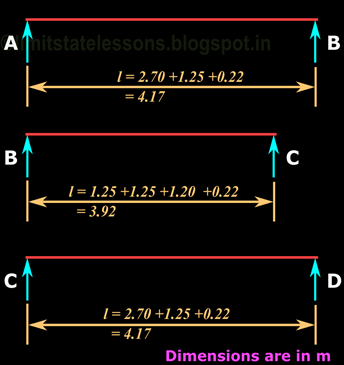
We will do the analysis and design of the three flights in Floor2. For this first we will draw the line diagram of each flight showing the effective spans. This is given in the fig.105 below:
Fig.105
Effective span of flights

Effective span of flights

From the fig.105, we can see that AB and CD have the same effective span,and has the largest value of 4.17m. So we will use this value to fix up the preliminary value of 't', the thickness of waist slab. For all the previous problems on longitudinal stairs, we used the thumb rule of t = l /20 to fix up a preliminary value. Now we will see a different method:
From the previous examples, we have seen that, a lower value of thickness may be sufficient to resist the bending moment, but that lower value will not satisfy the deflection check. That is., the deflection criterion is more important than the bending moment criterion, when finalising the thickness of the slab. So we will do the procedure for deflection check in a sort of 'reverse' manner to fix up a preliminary value for 't'. This can be done as follows:
We know that, for spans less than 10m, to satisfy the deflection check, the following condition should be satisfied: (Details here)
For simply supported members, (l/d) basic = 20.
Now we take kt. This can be calculated by using the expression given in SP24:
where
But in the above expressions, there are three unknowns. (a) pt, (b) Area of steel required, and (c) Area of steel provided. These three unknowns can be solved by making two simple assumptions.
First we assume the Area of steel provided for a 1m wide strip with total depth t = 200mm. If the concrete cover is 20mm, and 12mm (Fe 415) bars are provided, effective depth d = 200 –20 –6 = 174mm:
Assume that 12 mm bars are provided at a spacing of 150mm c/c. So we can make the bar area calculations (Details here):
=113.1 mm2
= 754 mm2 - - - - (4)
So pt = (Ast x 100) / (b d) = (754 x100)/(1000 x174) = 0.43% - - - - (5)
So we can say that the pt for a stair will have a value around 0.43%. It may be noted that 0.43% is only an approximate value. In some stairs it can go up to 0.50% or even more. But the next time we do a problem of longitudinal stairs, we can straight away assume pt = 0.43%. There is no need to assume a section and the steel provided, and do the area calculations above.
However, this is only for preliminary dimensions. The dimensions so obtained should be finalised only after detailed checks using the actual value of steel required and steel provided.
Now we assume that the Area of steel required is same as the Area of steel provided = 754 mm2
So fs will become 0.58 x fy = 0.58 x415 = 240.7 - - - - (6)
Substituting (5) and (6) in (2), we get kt = 1.3 - - - - (7)
Substituting (7) in (1) we get (l/d) provided should be less than or equal to 20 x 1.3 = 26
In our present problem, l = 4170mm
So 4170 /d ≤ 26
So d should be greater than or equal to 4170/26 = 160.4 mm
If d is to be greater than 160.4mm, t should be greater than 160.4 +6 +20 = 186.4mm - - - - (8)
If we use the thumb rule we will get total depth t = 4170/20 = 208.5mm - - - - (9)
Let us adopt the value in (8) and provide t = 190mm.
However, as mentioned above, the design using this value of 190mm should be finalized only after the checks using actual area of steel required and the actual area of steel provided.
For a uniform appearance, we can provide the same t for flight BC also. Thus, the load per 1m2 area will be same on all the flights. We will see the load calculation details in the next section.
Copyright ©2015 limitstatelessons.blogspot.com - All Rights Reserved


Hello Nikhil,
ReplyDeleteThe Eq No2 for calculating kt seems wrong the term 0.625 log 10(pt) should have a minus sign(-) instead of plus(+). Please correct it.
Thanks,
Sangram
Dear Sir, The negative sign comes when we take logarithm of (bd/100Ast). But here we take the logarithm of pt which is the reciprocal(100Ast/bd). Please give your opinion about this. Thanks.
DeleteAs flight BC is supported on inclined beam St,b...the structural behaviour of staircase slab BC would be cantilever or ...
ReplyDeleteThe inclined beam St,b is at the side of flight BC. The loads from flight BC are not transferred to that inclined beam. The loads from flight BC are transferred to masonry walls.
Delete